Networking in Packet Tracer
General configuration method — from VLSM preparation to bottom-up debugging, covering VLANs, routing and security. Click on a device in the diagram to jump to its configuration.
The second half puts it to work: fifteen exercises and eight debugging scenarios, built and tested in the sandbox docked to the right of this text.
Click a device in the diagram, or use the guided walkthrough below, to display the matching commands and explanation here.
Method and preparation
Method
- Preparation:
- calculate the number of IPs needed per subnet
- calculate the netmasks, the subnet addresses, and the IPs of all devices
- calculate the wildcards, and the route summaries
- Physical layer:
- place all the machines, add network cards if needed
- cable the machines
- Basic configuration:
- initialize the machines
- give a hostname, etc.
- Data link layer:
- configure CDP
- configure switch port security
- configure the VLANs
- Basic network configuration:
- configure the interfaces
- create the static/default routes
- Advanced network configuration:
- enable L3 switch routing
- enable RIP routing
- enable RIPng routing
- enable OSPF routing
- create the ACLs and apply them to the interfaces
- Application layer:
- configure the DHCP server/relay
- save a config to an FTP/TFTP server
- configure SSH, Telnet
- configure device security (minimum password length, session duration, etc.)
- Recovery: recover the config/password.
- Debug.
VLSM calculation
- VLSM explanation: if you add 1 to the last address of a subnet, you get the first address of the next subnet. Example:
first address SR4 172.121.0000 1111.0000 0000last address SR4 172.121.0000 1111.1111 1111first address SR5 172.121.0001 0000.0000 0000 - For each subnet:
- Calculate the number of bits needed for the subnet.
- Calculate the matching netmask.
- Calculate the first address using the last address of the previous subnet.
- Calculate the last address of the subnet.
- Example: here is a network to split into 4 subnets:
193.115.111.0255.255.255.0SR0 = 32 SR1 = 16 SR2 = 128 SR3 = 64 IPs - To split a network into subnets of different sizes, you must go from largest to smallest (order: subnets 2, 3, 0, 1).
- log₂128 = 7 bits are needed to encode subnet 2.
- Subnet 2:
mask 255.255.255.1000 0000first addr. 193.115.111.0000 0000last addr. 193.115.111.0111 1111 - log₂64 = 6 bits are needed to encode subnet 3.
- Subnet 3:
mask 255.255.255.1100 0000first addr. 193.115.111.1000 0000last addr. 193.115.111.1011 1111 - log₂32 = 5 bits are needed to encode subnet 0.
- Subnet 0:
mask 255.255.255.1110 0000first addr. 193.115.111.1100 0000last addr. 193.115.111.1101 1111 - log₂16 = 4 bits are needed to encode subnet 1.
- Subnet 1:
mask 255.255.255.1111 0000first addr. 193.115.111.1110 0000last addr. 193.115.111.1110 1111
Route summarization calculation
- Route summarization explanation: calculating the address to create a route to several networks (≈ default route) passing through only one router.
- Calculating a summary route:
- List the networks in binary.
- Count the number of matching bits on the left to determine the mask.
- Calculate the network address.
- Example: here are 4 networks, calculate the summary route:
172.20.0.0 172.21.0.0 172.22.0.0 172.23.0.0 - List of the networks in binary:
172.0001 0100.0.0172.0001 0101.0.0172.0001 0110.0.0172.0001 0111.0.0 - Number of matching bits on the left: 14 ⟹ mask = 255.252.0.0.
- Network address = 172.20.0.0.
- List of the networks in binary:
Wildcard calculation
- Example (1): calculate the wildcard for the following networks:
192.168.0.0/24 192.168.1.0/24 192.168.2.0/24 192.168.3.0/24 network 1 192 168 0000 0000 0 network 2 192 168 0000 0001 0 network 3 192 168 0000 0010 0 netmask 255 255 1111 1111 0 wildcard 0 0 0000 0011 255 - Example (2): calculate the min & max addresses that the following ACL blocks:
access-list<list_num>deny<ip><wildcard>access-list23deny35.8.2.33.7.15.31network 0010 0011 0000 1000 0000 0010 0000 0011 wildcard 0000 0011 0000 0111 0000 1111 0001 1111 ip min 0010 0000 0000 1000 0000 0000 0000 0000 ip max 0010 0011 0000 1111 0000 1111 0001 1111 - ip min: 32.8.0.0
- ip max: 35.15.15.31
Network simulator
Network sandbox
Build your own topology: place PCs, servers, switches and routers, cable them port by port, then click a device to open its console and configure it with the real IOS commands from this document. The ping then follows the configuration to the letter — and tells you exactly where it breaks.
Each device has a fixed set of interfaces: FastEthernet0 on a PC,
Fa0/1 through Fa0/24 plus Gi0/1-2 on a switch,
Gi0/0, Gi0/1, Se0/0/0 and Se0/0/1 on a router.
The Config tab offers the same settings as a form: both write to the
same configuration, visible at any time with show running-config.
IPv4 and IPv6 work in parallel. An interface can carry both (dual stack):
ipv6 unicast-routing enables routing, ipv6 address …/64 [eui-64] addresses
the interfaces — the fe80:: link-local address is automatically derived from the MAC —
and routing is done via ipv6 route or RIPng. The
IPv4 / IPv6 selector in the test panel picks which stack to test.
Where The sandbox is docked on the right of this page, next to every section — no need to scroll back here to use it. It stays there while you read, and the exercises further down load their topologies straight into it.
Commands supported by the simulator
This list is generated from the simulator's command table: it describes exactly what
the console accepts. In the terminal, ? shows the possible keywords at the point
where you are, Tab completes, and the usual abbreviations work
(conf t, int gi0/0, sh ip int br).
Physical layer
Packet Tracer
HardwareConfiguring a PCDisabling a PC's firewallAdding a network card to the router for serial connections+2 more
Hardware
- router = Cisco 1941
- switch = Cisco 2960
Configuring a PC
- Click on the PC, then click the Desktop tab at the top of the window.
- Click IP Configuration, the first option at the top left.
Disabling a PC's firewall
- Click on the PC, then click the Desktop tab at the top of the window.
- Click Firewall at the bottom right.
- Click Off at the top right to disable it.
Adding a network card to the router for serial connections
For routers to be able to communicate with each other, network cards used for serial connections must be added:
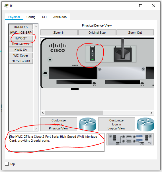
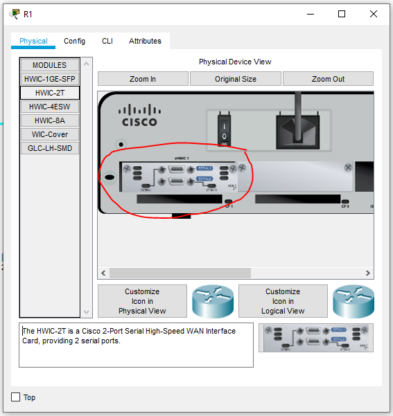
s0/1/0 and s0/1/1. To get the interfaces exactly as stated in the assignment, the network card must be placed on the right.Adding a network card to a server
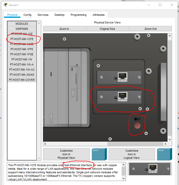
Before adding the new FastEthernet interface, you must press the red button to cut the power.
PC ports to use
- To configure Cisco devices, use the console cable (cyan) and connect it to the
RS232port. - To connect to the switch, use the
FastEthernet0port and the Copper Straight-Through cable (black).
Basic configuration
Basic configuration
Initialization (do this for every configuration)Configuring the console in synchronous modeSaving the configuration
Initialization (do this for every configuration)
enableconfigure terminalno ip domain-lookuphostname <name>banner motd %<message>%
Configuring the console in synchronous mode
line console 0logging synchronousexit
Saving the configuration
2 options:
copy running-config startup-configwrite
Data link layer
Testing layer 2 with CDP
cdp runshow cdpshow cdp neighborsshow cdp neighbors detail
VLAN configuration
Steps to configure a VLAN on a switchSteps to configure a VLAN on a routerChanging the native VLANRemoving a VLAN+2 more
Steps to configure a VLAN on a switch
- Disable DTP (Dynamic Trunking Protocol) and set the interfaces to access mode:
interface range f0/1-24switchport mode accessswitchport nonegotiate
- Create the VLANs:
vlan <num>name <name>
- Configure the interfaces according to the VLANs:
interface <interface>switchport access vlan <num>
- Configure interfaces in trunk mode:
interface <interface>switchport mode trunk
Steps to configure a VLAN on a router
- Enable the interface:
interface <interface>no shutdown
- Configure the sub-interfaces:
interface <interface>.<vlan_num>encapsulation dot1q <vlan_num>ip address <network> <mask>
Removing a VLAN
no vlan <vlan_num>(in VLAN creation mode)no interface vlan <vlan_num>(in configuration mode)
Note: both must be done.
Removing a VLAN sub-interface
no interface <interface>.<vlan_num>
Verifying the VLAN configuration
show vlanshow vlan briefshow interface trunkshow interface switchport
Switch port security
Disabling unused portsPort-security configurationViolation mode configurationVerifying switch port security configuration
Disabling unused ports
interface range f0/<start>-<end>shutdown
Port-security configuration
To enable port-security on a port, use the 1st command; it only works if the port is in access mode (not trunk).
switchport port-securityswitchport port-security maximum <num>switchport port-security mac-address [sticky]
| configuration | command |
|---|---|
| static | switchport port-security mac-address <mac_address> |
| dynamic | switchport port-security mac-address sticky |
| both | switchport port-security mac-address sticky <mac_address> |
Violation mode configuration
switchport port-security violation {protect | restrict | shutdown}
| blocks traffic | syslog message | ++ violation counter | port shutdown | |
|---|---|---|---|---|
| protect | yes | no | no | no |
| restrict | yes | yes | yes | no |
| shutdown | yes | yes | yes | yes |
Verifying switch port security configuration
show interfaces switchportshow port-securityshow port-security addressshow port-security interface <interface>
Basic network configuration
Basic network configuration
Configuring a network interfaceAdding a default gatewayIPv6 addressesTesting the network connection
Configuring a network interface
For a switch, use the vlan1 interface (or the management VLAN).
interface <interface>ip address <ip> <netmask>ipv6 address <ip>/<netmask> [eui-64]clock rate <clock_rate>no shutdowndescription <interface_description>exit
Reset an interface:
default interface <interface>
Adding a default gateway
ip default-gateway <gateway>
IPv6 addresses
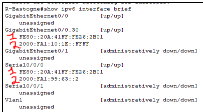
| (1) | FE80::/10 | link-local | auto-configured/mandatory/local network |
| (2) | 2000::/3 | global unicast | public address |
ipv6 address <ip> link-localipv6 address <ip>/<netmask>ipv6 address <network>/<netmask> eui-64
Testing the network connection
These commands can be used with both IPv4 and IPv6.
- Common to all devices:
ping <ip> - Cisco devices only:
traceroute <ip> - PCs only:
tracert <ip>
Static routes
Configuring a static routeAdding a backup routeTesting routing (examining network state)
Configuring a static route
- Recursive route:
ip route <target_network_ip> <netmask> <router_ip>ipv6 route <network>/<netmask> <router_ip>
- Recursive default route:
ip route 0.0.0.0 0.0.0.0 <router_ip>ipv6 route ::/0 <router_ip>
- Directly connected route:
ip route <target_network_ip> <netmask> <router_interface>ipv6 route <network>/<netmask> <router_interface>
- Directly connected default route:
ip route 0.0.0.0 0.0.0.0 <router_interface>ipv6 route ::/0 <router_interface>
Adding a backup route
ip route <network> <netmask> <interface/router_ip> <admin_distance>
| route type | distance |
|---|---|
| connected interface | 0 |
| static route | 1 |
| RIP | 120 |
| unknown | 255 |
The lower the administrative distance, the more the route is preferred.
Testing routing (examining network state)
On routers:
show ip interface briefshow ip protocolsshow ip route [summary]debug ip protocol(cancel withno debug ip protocol)
IPv6:
show ipv6 ripshow ipv6 route [summary]show ipv6 protocolsshow ipv6 interface brief
Advanced network configuration
Enabling routing on an L3 switch
ip routing
RIP configuration
RIP configuration steps
- Initialization:
router ripversion 2no auto-summary
- Add connected routes, and prevent sending routing information on certain interfaces:
network <connected_network_ip>passive-interface <interface>
- Propagate routes:
redistribute connectedredistribute staticdefault information-originate
Verifying that RIP is working properly
debug ip ripshow ip rip neighborsshow ip rip database
RIPng configuration (RIP IPv6)
RIPng configuration steps
- Initialization:
ipv6 unicast-routing - Enable on certain interfaces:
interface <interface>ipv6 rip <name> enable
- Route propagation:
ipv6 router rip <name>redistribute staticredistribute connectedipv6 rip <name> default-information originate
Note: the <name> parameter that appears in every command is the process name and must be the same on all routers/interfaces.
Verifying that RIPng is working properly
debug ipv6 ripshow ip protocolsshow ipv6 ripshow ipv6 routeshow ipv6 route ripshow ipv6 rip [name][database]
OSPF configuration
OSPF configuration steps
- Initialization:
router ospf <process-id>router-id <router-id>auto-cost reference-bandwidth <bandwidth>
- Add connected routes, and prevent sending routing information on certain interfaces:
network <network> <wildcard> area <area-id>passive-interface <interface>
- Route propagation:
redistribute connectedredistribute staticdefault-information originate
Choosing the bandwidth:
- gigabit ethernet:
auto-cost reference-bandwidth 1000 - 10 gigabit ethernet:
auto-cost reference-bandwidth 10000 - back to default:
auto-cost reference-bandwidth 100
Changing OSPF priority
ip ospf priority <priority>
Notes:
- DR = designated router
- BDR = backup designated router
- Default priority = 1
- Max priority = 255, automatically elected DR
- Min priority = 0, cannot be elected DR
- At equal priority, the router with the highest
<router-id>is elected.
Verifying that OSPF is working properly
show ip protocolsshow ip ospf neighborshow ip ospfshow ip ospf interface
ACL configuration (access control list)
Adding ACLs to restrict routing
Command to create an ACL:
access-list <list_num> {deny | permit} <ip> <wildcard>access-list <list_num> {deny | permit} anyaccess-list <list_num> {deny | permit} host <ip>
list_num∈ [1,99] ⟹ standard ACL, controls the source IPlist_num∈ [100,199] ⟹ extended ACL, controls the source/destination IP, or the port, or the service
On a VLAN or ethernet interface (or directly on a physical interface for a router):
ip access-group <access_list_num> {in | out}
in= inbound packetsout= outbound packets
Note: for a switch, the ACL must be added on a VLAN and then the FastEthernet interface added to the VLAN.
Configuring a named ACL
Configure the ACL and its rules:
ip access-list {standard | extended} {<list_num> | <list_name>}[<rule_num>] {deny | permit} <ip> <wildcard>[<rule_num>] {deny | permit} any[<rule_num>] {deny | permit} host <ip>
Remove the ACL or rules:
no <rule_num>no {deny | permit} ...no ip access-list {standard | extended} {<list_num> | <list_name>}
To add the ACL to the interface:
ip access-group {<list_num> | <list_name>} {in | out}
Steps to configure an IPv6 ACL
- Create the named ACL:
ipv6 access-list <acl_name> - Create rules:
{permit | deny} ipv6 <source> <destination>- with source/destination =
{any | host <ip> | <ip>/<netmask>}
- Add the ACL to the interfaces:
ipv6 traffic-list <acl_name> {in | out}
IPv6 ACL rules to block HTTP/HTTPS requests
deny tcp <source> <destination> eq <port>deny tcp <source> <destination> eq wwwdeny tcp <source> <destination> eq 443
Removing/modifying an ACL
Remove an ACL:
no access-list <acl_num>
Remove part of an ACL:
ip access-list {standard | extended} <acl_num>no <rule_num>
Verifying the ACL list
show access-list
Application layer
Device security
Disconnect after 5 min of inactivityBlock login for 30 s after 2 failures within 2 min
Passwords
- Encrypt passwords:
service password-encryption - Require a minimum password length:
security passwords min-length 10 - Assign an encrypted privileged EXEC password:
enable secret <pwd> - Assign a console password and enable login:
line console 0password <pwd>login
- Assign a VTY password and enable login (router):
line vty 0 4password <pwd>login local
- Assign a VTY password and enable login (switch):
line vty 0 15password <pwd>login local
Disconnect after 5 min of inactivity
line console 0exec-timeout 5 0line vty 0 4exec-timeout 5 0exit
Block login for 30 s after 2 failures within 2 min
login block-for 30 attempts 2 within 120
SSH / Telnet
Enabling Telnet login
line vty 0 15transport input telnetpassword <password>login
Enabling SSH login
- Add a domain name, and create a user for SSH login:
ip domain-name <greg.com>username <username> privilege 1 secret <pwd>
- Configure the VTY lines to allow SSH connections:
line vty 0 4 - Allow SSH only (reject Telnet):
transport input ssh - The login must be done against a local account:
login localexit
- Generate an RSA key:
crypto key generate rsa [general-keys modulus <num_bits>]
FTP / TFTP
Copying the configuration to an FTP server
ip ftp username <username>ip ftp password <password>copy running-config ftp:(orstartup-config)
Retrieving the configuration from an FTP server
ip ftp username <username>ip ftp password <password>copy ftp: running-config
Copying/retrieving the configuration to/from a TFTP server
copy running-config tftp:copy tftp: running-config
Checking the configuration
show running-config
DHCP configuration
Configuring a DHCP relay
service dhcpip helper-address <dhcp_server_ip>(on an interface, not mandatory)
Notes:
- it can take a while for a machine's configuration to complete (alt+d advances 30 sec)
- the client machine absolutely must be in the correct VLAN
- the DHCP relay is needed when the DHCP server is not in the same VLAN as the machines
Configuring a DHCP service
service dhcpip dhcp pool <pool_name>network <network> <mask>dns-server <address>default-router <address>ip dhcp excluded-address <first_ip> [<end_of_ip_range>]
Notes:
- you can create one pool per VLAN by giving the pool the VLAN's name (e.g.: VLAN name = pool name = vlan10)
- to create a global pool, simply don't give it a VLAN name (e.g.: pool name = globalpool)
- an IP address must absolutely be configured on the router's interfaces (+ the VLANs) before DHCP will work
- no need to exclude the DHCP server's own IP address, the DHCP service does this automatically
Verifying the DHCP configuration
show ip dhcp poolshow ip dhcp pool <pool_name>show ip dhcp bindingshow ip dhcp conflictshow ip dhcp relay information trusted-sources
Recovery
Config / password recovery
On a router (with rommon)
- Power the machine back on or use
reload. - While the IOS image is decompressing (lots of
###):- In the lab: ctrl+break
- In Packet Tracer: ctrl+c (otherwise, try ctrl+shift+f6+c)
confreg 0x2142resetenablecopy startup-config running-config- Reset the passwords.
write memory, orcopy running-config startup-config
Notes:
- register = 2142 ⟹ boot without the startup-config
- register = 2102 ⟹ boot with the startup-config
- register = 2100 ⟹ boot into rommon mode
On a router (NOT rommon)
Only if already connected:
enableconfigure terminalconfig-register 2142do reloadenablecopy startup-config running-config- Reset the passwords.
write memory, orcopy running-config startup-config
On a switch (recovery mode)
- Connect to the console port at 9600 baud.
- Power the machine back on or use
reload. - Hold the mode button for 3 seconds.
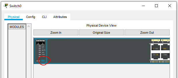
flash_initload_helper(not in Packet Tracer)dir flash:rename flash:config.text flash:<name>resetenablecopy flash running-config(you'll be asked for the file name afterward)- Change the passwords, then save the new configuration.
Debugging the network configuration
Click a device, or follow the walkthrough below, to display the debugging checklist for its layer.
Determining the source of the problem — intermediate approach
If there's a problem at the end of the exercise:
- Enter simulation mode in Packet Tracer, and try pinging between the machines (layer 3).
- If the ping works, the problem is in the application layer (DHCP, FTP, SSH, etc.).
Example — DHCP problem:
- filter packets by the DHCP protocol
- check whether the packet has an issue at the server or the relay
- If the ping doesn't work, check the network layer:
- check the IP configuration of the machines between which the ping doesn't get through
- check the routing table (static routes & RIP protocol)
- check the ACLs
- If it still doesn't work (or if it gets stuck at a switch), move on to the data link layer:
- check that the VLANs are configured correctly
- check that switch port security is configured correctly
- check that the machine correctly finds its neighbors with the CDP protocol
- In principle, there's no need to go down to the physical layer, but if needed...
- check that the machines are powered on
- check that the correct interfaces are enabled
- check that the cables are plugged into the correct interfaces
Debugging the network configuration in the lab — bottom-up approach
- Physical layer — check that the cabling is correct:
- check whether the cables are in the correct router ports (g0/0 or g0/1)
- check whether the cables are plugged into the correct ports on the patch panels
- check whether the cable colors are correct (console = blue, communication = green)
- check whether the cable is properly plugged into the PC
- check whether the router is properly powered on
- check whether an LED lights up on the router when the cable is plugged in — if not, change the cable
- Data link layer — check the network card configuration:
- in the PC's search bar, type
ncpa.cpl - to identify which network card to configure: unplug the cable connected to the router
- plug the cable back in and configure the network card where the change occurred
- in the PC's search bar, type
- Network layer — check the IP configuration:
- use
ipconfigon the PCs, andshow ip interface briefon the routers - use
show cdp neighbors detailto display the IPs of neighboring machines - use
ping,traceroute [-h <max_hop_count>],tracert [-h <max_hop_count>] - display the routes on the routers, reconfigure RIP, or add static routes
- use
- Application layer:
- disable the firewalls on the PCs/servers
- check that the service is properly enabled
- check that the client machines are properly configured (PC on DHCP, matching DNS IP)
- reconfigure DNS, DHCP, FTP, etc.
Appendices
Packet Tracer quirks
- Cannot use
login block-for 30 attempts 2 within 120on a switch in Packet Tracer. - Cannot add secondary IP addresses in Packet Tracer.
- Cannot use the
load_helpercommand in Packet Tracer. - Cannot create sub-interfaces on FastEthernet interfaces in Packet Tracer.
Cisco console modes
router> | user EXEC |
router# | privileged EXEC |
router(config)# | configuration (privileged) |
router(config-if)# | interface configuration |
router(config-router)# | routing protocol configuration |
router(config-rtr)# | IPv6 routing protocol configuration |
router(config-line)# | terminal line configuration |
router(config-std-nacl)# | standard named ACL configuration |
router(config-ext-nacl)# | extended named ACL configuration |
router(vlan)# | VLAN creation |
router(dhcp-config)# | DHCP service configuration |
rommon 1> | rommon mode (= ROM monitor) |
switch: | rommon mode (= ROM monitor) |
switch(config-vlan)# | VLAN configuration |
Terminal help
?= shows the commands that can be used in the current mode<command_start>?= shows the commands that start with command_start<command> ?= shows the arguments/options the command takes<command>(no arguments) = suggests default arguments that can be modified
Notes:
- for some commands (e.g.:
copy), there is no default argument (howevercopy ?works) - but:
copy flash ftpworks, just likecopy flash running-config copy flash flashdoes not work
VLSM cheat sheet
| mask as / | mask | wildcard | number of IPs |
|---|
Packet Tracer exercises
Fifteen exercises and eight debugging scenarios, all doable in the sandbox docked on the right — no Packet Tracer install needed. Every topology is built, configured and tested with the same IOS commands as the method above.
How to use the exercises
Reading an exercise
Every exercise has the same five blocks. Work down them in order; the point of the shape is that you should be able to do the Do block without reading the solution.
| Block | What it is for |
|---|---|
| Goal | One sentence. What works at the end that didn't at the start. |
| Build | The topology and addressing to set up. |
| Do | What to configure — as tasks, not as commands to copy. |
| Verify | The exact show / ping that proves it. |
| If it fails | The two to four mistakes that actually cause the failure. |
Solutions sit in a collapsed block at the end of each exercise. Open it after you have tried, not before — the failure modes listed under If it fails are the real content.
Sandbox conventions you need to know
These are constraints of the simulator, not of real IOS. Part 02 lists the interfaces each device has and what the engine does not implement; what follows is the subset of that which changes what an exercise can ask you to prove.
- PCs and servers have no
configure terminal. Their shell is the Windows-style one:ipconfig,ipconfig /all,ipconfig /renew,ipconfig /release,ping,tracert,arp -a. Set a PC's address in the Config tab, not from its command prompt. - The only traffic generator is ping (ICMP). An ACL written as
deny tcp … eq wwwis accepted and shown byshow access-lists, but you cannot demonstrate it with a ping. Useicmporiprules whenever an exercise asks you to prove an ACL works. - Routers are the DHCP servers.
ip dhcp poolis an IOS command; the "Server" device here is a host, not a Cisco device. - Some commands are recorded but not enforced.
clock rateon a serial is the notable one: it appears in the config and inshow interfaces, but the link comes up without it. A few real-lab faults therefore cannot be reproduced; exercises flag this where it applies. - Nothing is authenticated. Password exercises are therefore verified by reading
show running-config, not by logging in.
Layers 1–3, one subnet at a time
Three exercises that go deliberately slowly, so that "why does a default gateway exist" gets answered by an experiment rather than by a definition.
EX 1
Two PCs and one cable
~5 min
Goal
Get a ping between two directly-cabled PCs, with no switch and no router.
Build
| Device | Interface | Address | Mask |
|---|---|---|---|
| PC0 | FastEthernet0 | 192.168.1.10 | 255.255.255.0 |
| PC1 | FastEthernet0 | 192.168.1.11 | 255.255.255.0 |
Cable mode → click PC0, pick FastEthernet0, click PC1, pick
FastEthernet0.
Do
Address both PCs from the Config tab. Leave the default gateway empty — you don't need one yet, and knowing why is the point of exercise 3.
Verify
ipconfigon PC0 shows the address you set.ping 192.168.1.11from PC0 replies 4/4.arp -aon PC0 now lists PC1.
If it fails
- Masks differ between the two PCs → they don't agree on who is local.
- Addresses aren't in the same /24 (192.168.1.10 and 192.168.2.11).
- The cable landed on the wrong port — click the link to check both ends.
Solution
No CLI at all. Config tab on each PC:
PC0:  IP 192.168.1.10   Mask 255.255.255.0
PC1:  IP 192.168.1.11   Mask 255.255.255.0
Then from PC0's terminal:
ping 192.168.1.11Two hosts on the same subnet ARP for each other directly — no gateway is consulted, which is exactly why this works with the gateway field blank.
EX 2
Add a switch, and name it
~10 min
Goal
Three PCs talking through a switch, and a switch you have actually configured rather than just dropped on the canvas.
Build
SW1 with PC0 → Fa0/1, PC1 → Fa0/2, PC2 → Fa0/3.
Addresses 192.168.1.10 / .11 / .12, mask /24.
Do
- On SW1: run the standard initialisation — hostname,
no ip domain-lookup, a MOTD banner. - Make the console usable:
line console 0+logging synchronous. - Give SW1 a management address on
interface vlan 1(192.168.1.2/24) so you can ping the switch itself. - Save the configuration.
Verify
show ip interface briefon SW1 — Vlan1 isup/up.ping 192.168.1.2from PC0 replies.show mac address-tableon SW1 lists all three PCs after they have pinged.show running-configreflects everything;show startup-configmatches it only after you save.
If it fails
- Vlan1 left
shutdown—no shutdownis required on the SVI. - You saved with
writebut then kept configuring; re-checkshow startup-config. - The MAC table is empty because nothing has been sent yet — ping first, then look.
Solution
enable
configure terminal
hostname SW1
no ip domain-lookup
banner motd %Students only%
line console 0
 logging synchronous
 exit
interface vlan 1
 ip address 192.168.1.2 255.255.255.0
 no shutdown
 exit
end
copy running-config startup-config
The MAC address table is learned, not configured: it stays empty until frames actually cross the switch. That observation is what this exercise is really about.
EX 3
Two subnets and a router — the gateway lesson
~15 min
Goal
Ping across two subnets — and, first, fail to, so that the default gateway stops being a form field you fill in from habit.
Build
PC0 ── SW1 ── R1(Gi0/0)        R1(Gi0/1) ── SW2 ── PC1
   192.168.1.0/24                    192.168.2.0/24
| Device | Interface | Address |
|---|---|---|
| PC0 | Fa0 | 192.168.1.10/24 |
| R1 | Gi0/0 | 192.168.1.1/24 |
| R1 | Gi0/1 | 192.168.2.1/24 |
| PC1 | Fa0 | 192.168.2.10/24 |
Do
- Address the router's two interfaces and bring both up.
- Address the PCs but leave the default gateway blank. Ping PC0 → PC1. Read the failure message the sandbox prints; it names the reason.
- Now set the gateways (192.168.1.1 and 192.168.2.1) and ping again.
Verify
show ip interface briefon R1 — both interfacesup/up.show ip routeon R1 lists twoC(connected) routes and nothing else. No static routes are needed here — that's the second lesson.tracert 192.168.2.10from PC0 shows exactly one hop before the destination.
If it fails
- Interfaces left administratively down — routers boot with everything shut, switches don't.
- Gateway set to the far-side router interface (PC0 pointing at 192.168.2.1) — it must be the address on PC0's own subnet.
- Only one gateway set: the ping leaves fine and the reply has nowhere to go. Ping failures are round trips.
Solution
enable
configure terminal
hostname R1
interface gi0/0
 ip address 192.168.1.1 255.255.255.0
 no shutdown
 exit
interface gi0/1
 ip address 192.168.2.1 255.255.255.0
 no shutdown
 end
show ip route
PCs, Config tab: gateway 192.168.1.1 on PC0, 192.168.2.1 on PC1.
A router knows its directly connected subnets automatically. Static routes only become necessary when a subnet is not on one of its own interfaces — exercise 7.
VLANs
Two of these three exercises end with a ping that is supposed to fail. That failure is the deliverable.
EX 4
Two VLANs on one switch
~15 min
Goal
Split one switch into two isolated networks, and prove the isolation by making a ping fail on purpose.
Build
SW1 with four PCs: PC0 Fa0/1, PC1 Fa0/2 (VLAN 10,
192.168.10.0/24), PC2 Fa0/3, PC3 Fa0/4 (VLAN 20,
192.168.20.0/24).
Do
- Before creating anything: put
Fa0/1–Fa0/24in access mode and disable DTP, in oneinterface rangecommand. - Create VLAN 10 named
ADMINand VLAN 20 namedPROF. - Assign the four access ports.
Verify
show vlan brief— the ports are listed under the right VLAN.- PC0 → PC1 pings. PC2 → PC3 pings.
- PC0 → PC2 fails, even though the addresses look reachable and both PCs are on the same switch. This failure is the deliverable.
If it fails
- The VLAN exists but no port was assigned —
show vlan briefshows an empty VLAN. - PC0 → PC2 succeeds: the ports are still in VLAN 1, or the two VLANs share one subnet.
switchport access vlan 10refused: the port is in trunk or dynamic mode.
Solution
enable
configure terminal
interface range fa0/1-24
 switchport mode access
 switchport nonegotiate
 exit
vlan 10
 name ADMIN
 exit
vlan 20
 name PROF
 exit
interface range fa0/1-2
 switchport access vlan 10
 exit
interface range fa0/3-4
 switchport access vlan 20
 end
show vlan brief
Two VLANs = two broadcast domains = two separate networks that happen to share hardware. Nothing short of a router (exercise 6) will move a packet between them.
EX 5
Carry the VLANs between two switches
~15 min
Goal
Same VLAN, two switches, one cable between them.
Build
SW1 Gi0/1 ↔ SW2 Gi0/1. PC0 on SW1 Fa0/1 (VLAN 10),
PC1 on SW2 Fa0/1 (VLAN 10), PC2 on SW1 Fa0/3 (VLAN 20), PC3 on
SW2 Fa0/3 (VLAN 20). Same subnets as exercise 4.
Do
- Create VLANs 10 and 20 on both switches — VLAN definitions don't cross the cable by themselves.
- Make
Gi0/1a trunk on both ends. - Restrict the trunk to VLANs 10 and 20 only.
- Change the native VLAN to 99 on both ends and observe that nothing breaks — then change it on one end only and see what the simulator reports.
Verify
show interfaces trunkon both — same allowed list, same native VLAN.- PC0 → PC1 pings across the trunk. PC0 → PC3 still fails.
If it fails
- One end is access, the other trunk.
- VLAN 10 created on SW1 but not SW2 — frames arrive tagged for a VLAN the far switch doesn't know.
- You allowed
10,20on the trunk but forgot the native VLAN is also carried.
Solution
On both switches:
configure terminal
vlan 10
 name ADMIN
 exit
vlan 20
 name PROF
 exit
vlan 99
 name NATIVE
 exit
interface gi0/1
 switchport mode trunk
 switchport trunk allowed vlan 10,20,99
 switchport trunk native vlan 99
 end
show interfaces trunk
A native VLAN mismatch is the classic silent fault: the link stays up, and only some traffic goes missing.
EX 6
Router-on-a-stick
~20 min
Goal
Make VLAN 10 and VLAN 20 talk to each other, over the single cable you already have.
Build
Take exercise 4's switch and add R1: SW1 Gi0/2 ↔ R1 Gi0/0.
| VLAN | Subnet | Router sub-interface |
|---|---|---|
| 10 | 192.168.10.0/24 | Gi0/0.10 → 192.168.10.1 |
| 20 | 192.168.20.0/24 | Gi0/0.20 → 192.168.20.1 |
Do
Gi0/2on SW1 becomes a trunk.- On R1: bring up the physical
Gi0/0first, with no address on it. - Create the two sub-interfaces, tag each with
encapsulation dot1q, address each. - Point each PC at the sub-interface address for its VLAN.
Verify
show ip routeon R1 — two connected routes, one per sub-interface.- PC0 (VLAN 10) → PC2 (VLAN 20) now pings, where in exercise 4 it could not.
tracertfrom PC0 to PC2 shows the router as a hop, even though both PCs hang off one switch.
If it fails
no shutdownon the physical interface was skipped. Sub-interfaces of a down interface are down, and this is the single most common failure in this exercise.encapsulation dot1q 10put onGi0/0.20— the sub-interface number is a convention, theencapsulationnumber is what actually matters.- SW1
Gi0/2still in access mode: only one VLAN reaches the router. - Do not create VLANs on the router. It has no VLAN database.
Solution
SW1:
configure terminal
interface gi0/2
 switchport mode trunk
 end
R1:
configure terminal
interface gi0/0
 no shutdown
 exit
interface gi0/0.10
 encapsulation dot1q 10
 ip address 192.168.10.1 255.255.255.0
 exit
interface gi0/0.20
 encapsulation dot1q 20
 ip address 192.168.20.1 255.255.255.0
 end
show ip route
Gateways: PC0/PC1 → 192.168.10.1, PC2/PC3 → 192.168.20.1.
Then, to see it come apart cleanly: no interface gi0/0.20 and re-ping.
Routing
Static routes first, written by hand in both forms; then the same topology handed over to RIP, and then to OSPF.
EX 7
Static routes over a serial link
~20 min
Goal
Two sites, a WAN link between them, and routes you wrote by hand.
Build
PC0 ── SW1 ── R1 ══Se0/0/0══ R2 ── SW2 ── PC1
 192.168.1.0/24   10.0.0.0/30   192.168.2.0/24
| Device | Interface | Address |
|---|---|---|
| R1 | Gi0/0 | 192.168.1.1/24 |
| R1 | Se0/0/0 | 10.0.0.1/30 (DCE end — set clock rate 64000) |
| R2 | Se0/0/0 | 10.0.0.2/30 |
| R2 | Gi0/0 | 192.168.2.1/24 |
Do
- Address and enable everything; set
clock rate 64000on R1's serial (the DCE end). - Confirm the two routers ping each other across the serial link before adding any route.
- Add one static route on each router for the far LAN. Write R1's as a recursive
route (next-hop IP) and R2's as directly connected (exit interface), then compare
them in
show ip route. - Replace both with default routes and check it still works.
- Add a second, deliberately wrong backup route with administrative distance 200 and
confirm
show ip routeignores it while the primary is up.
Verify
show ip interface brief— serialup/uponce both ends areno shutdown.show interfaces se0/0/0on R1 shows the clock rate you set.show ip routeshowsSentries; the AD-200 route does not appear.- PC0 → PC1 pings;
tracertshows two router hops.
down/down until the DCE end supplies a clock. This engine stores and displays
clock rate but does not enforce it, so the link comes up without it. Set it
anyway — it's the habit that matters in the lab — but don't expect the omission to show up as
a fault here.If it fails
- One end still
shutdown— routers boot with every interface administratively down. - A route on one router only: pings leave, replies die. Routing is per-direction.
/30mask typed as 255.255.255.0 — the two routers then disagree about the link subnet.
Solution
R1:
configure terminal
interface gi0/0
 ip address 192.168.1.1 255.255.255.0
 no shutdown
 exit
interface se0/0/0
 ip address 10.0.0.1 255.255.255.252
 clock rate 64000
 no shutdown
 exit
ip route 192.168.2.0 255.255.255.0 10.0.0.2
R2:
configure terminal
interface gi0/0
 ip address 192.168.2.1 255.255.255.0
 no shutdown
 exit
interface se0/0/0
 ip address 10.0.0.2 255.255.255.252
 no shutdown
 exit
ip route 192.168.1.0 255.255.255.0 se0/0/0
Default-route version (both routers, since each has exactly one way out):
no ip route 192.168.2.0 255.255.255.0 10.0.0.2
ip route 0.0.0.0 0.0.0.0 10.0.0.2
Backup with a worse AD, on R1:
ip route 192.168.2.0 255.255.255.0 192.168.1.99 200It is installed in the config but not in the routing table — show ip route
proves it. Lower administrative distance wins.
EX 8
RIPv2 across three routers
~20 min
Goal
Delete every static route and let the routers find each other.
Build
R1 ═ R2 ═ R3 in a line over serials (10.0.0.0/30 and 10.0.0.4/30), one LAN hanging off R1 (192.168.1.0/24) and one off R3 (192.168.3.0/24).
Do
- Enable RIP on all three: version 2,
no auto-summary. - Advertise every directly connected network with
network. - Set
passive-interfaceon the LAN-facing interfaces — there are no routers out there to talk to. - Ping PC0 → PC1 across two hops neither router was told about.
Verify
show ip protocols— version 2, auto-summary off, the passive list, the advertised networks.show ip routeon R2 —Rentries for both LANs.show ip rip database, anddebug ip ripto watch updates (turn it off withno debug ip rip).
If it fails
version 2omitted: v1 doesn't carry masks, and anything non-classful breaks.auto-summaryleft on: /30 links get summarized into /8 nonsense.- A
networkstatement missing on a middle router — R2 must advertise both serial subnets. passive-interfaceapplied to a serial by mistake — that silences the neighbour you need. (Scenario D8 is exactly this.)
Solution
R2 (the middle router; R1 and R3 follow the same shape):
configure terminal
router rip
 version 2
 no auto-summary
 network 10.0.0.0
 network 10.0.0.4
 end
show ip protocols
R1:
router rip
 version 2
 no auto-summary
 network 192.168.1.0
 network 10.0.0.0
 passive-interface gi0/0
network takes a classful network address and means "run RIP on any interface
inside it" — it is not a list of routes to advertise, which is the misconception this
exercise is aimed at.
EX 9
OSPF, single area
~25 min
Goal
The same topology as exercise 8 under OSPF, with wildcard masks computed by hand.
Do
- Remove RIP (
no router rip). router ospf 1, a hand-setrouter-idper router (1.1.1.1, 2.2.2.2, 3.3.3.3).network … area 0for every connected subnet — compute each wildcard yourself before typing it; the wildcard section has the method.auto-cost reference-bandwidth 1000on all three, since there are gigabit interfaces.passive-interfaceon the LANs.- Raise the OSPF cost on one serial and watch the path change in
show ip route.
Verify
show ip ospf neighbor— each router sees its neighbours.show ip ospf interface,show ip protocols.show ip route—Oentries.
If it fails
- Wildcard written as a subnet mask. For /30, it is
0.0.0.3, not255.255.255.252. - Reference bandwidth set on only some routers — costs then don't compare and path selection goes strange.
- Two routers with the same
router-id. - Mismatched area numbers on the two ends of a link.
Solution
R1:
configure terminal
no router rip
router ospf 1
 router-id 1.1.1.1
 auto-cost reference-bandwidth 1000
 network 192.168.1.0 0.0.0.255 area 0
 network 10.0.0.0 0.0.0.3 area 0
 passive-interface gi0/0
 end
show ip ospf neighbor
Wildcards: /24 → 0.0.0.255, /30 → 0.0.0.3, /26 →
0.0.0.63. It is 255.255.255.255 minus the mask, octet by octet.
To move traffic: interface se0/0/0 + ip ospf cost 500 on one
router, then show ip route again.
Services and security
DHCP, ACLs, port security, dual-stack IPv6 and a router you hand in for marking.
EX 10
DHCP, then DHCP across a router
~20 min
Goal
Stop typing addresses into PCs. Then make it work from the other side of a router, which is where it usually breaks.
Build
Part 1: R1 Gi0/0 → SW1 → PC0, PC1. Part 2: add R2 and a second LAN with PC2,
with R1 still the only DHCP server.
Do — part 1
service dhcpon R1.- A pool
LAN1for 192.168.1.0/24, gateway 192.168.1.1, DNS 8.8.8.8. - Exclude 192.168.1.1–192.168.1.9 so the infrastructure range stays free.
- Switch PC0 and PC1 to DHCP in the Config tab, then
ipconfig /renew.
Do — part 2
- Second LAN on R2 (192.168.2.0/24), routing between R1 and R2 already working.
- PC2 set to DHCP → it gets nothing. DHCP discovery is broadcast; broadcasts don't cross routers.
- Add
ip helper-addresson R2's LAN interface pointing at R1, and a matching pool on R1.
Verify
show ip dhcp poolandshow ip dhcp bindingon R1 — the leases, with which MAC took what.ipconfig /allon the PCs shows address, mask, gateway and which server issued the lease.ipconfig /releasethen/renew— the address comes back.
If it fails
- Pool subnet doesn't match the interface's subnet — the router won't serve a pool it isn't on.
default-routeromitted: PCs get an address and can't leave the subnet. The symptom looks like a routing problem.- Part 2 with no second pool: the relay works, but R1 has nothing to hand out for 192.168.2.0/24.
- Excluded range overlaps everything you wanted to give out.
Solution
R1, part 1:
configure terminal
service dhcp
ip dhcp excluded-address 192.168.1.1 192.168.1.9
ip dhcp pool LAN1
 network 192.168.1.0 255.255.255.0
 default-router 192.168.1.1
 dns-server 8.8.8.8
 end
show ip dhcp pool
R1, part 2 — a second pool for the remote LAN:
configure terminal
ip dhcp excluded-address 192.168.2.1 192.168.2.9
ip dhcp pool LAN2
 network 192.168.2.0 255.255.255.0
 default-router 192.168.2.1
 dns-server 8.8.8.8
 exit
R2 — relay the broadcast to R1:
configure terminal
interface gi0/0
 ip helper-address 192.168.1.1
 end
Then on PC2: ipconfig /renew. The relay stamps the request with its own
interface address, which is how R1 knows to answer from LAN2 and not
LAN1.
EX 11
ACLs that you can actually watch working
~25 min
Goal
Block one host, then one subnet, then convert to a named ACL — verifying each with a ping that stops working.
Build
Exercise 3's topology (two LANs, one router), or exercise 7's if you want two routers.
Do
- Standard ACL. Block PC0 (192.168.1.10) from reaching 192.168.2.0/24, while every other host on 192.168.1.0/24 still gets through. Apply it as close to the destination as you can — a standard ACL only matches source, so placing it near the source blocks too much.
- Extended ACL. Delete the standard one. Now block only ICMP from 192.168.1.0/24 to host 192.168.2.10, applied inbound on the router's LAN interface.
- Named ACL. Rewrite step 1 as a named standard ACL, then remove a single rule from it by sequence number — the thing numbered ACLs can't do.
- Implicit deny. Write an ACL with only a
deny host …line and nopermit. Everything stops. Explain why to yourself before addingpermit any.
Verify
show access-listsafter each step.show running-config— which interface carriesip access-group, and in which direction.- The pings: PC0 → PC1 fails, PC-other → PC1 succeeds.
If it fails
- No
permit anyat the end → the implicit deny drops everything. - Applied
inwhere it neededout. Direction is relative to the router's interface, not to your mental picture of the traffic. (Scenario D6 is exactly this.) - The ACL exists but was never bound with
ip access-group.show access-listslooks fine and nothing is filtered. - Rules are evaluated top-down, first match wins: a
permit anyabove adeny hostmakes the deny dead.
Solution
Step 1 — standard, near the destination:
configure terminal
access-list 10 deny host 192.168.1.10
access-list 10 permit any
interface gi0/1
 ip access-group 10 out
 end
show access-lists
Step 2 — extended, near the source:
configure terminal
no access-list 10
access-list 100 deny icmp 192.168.1.0 0.0.0.255 host 192.168.2.10
access-list 100 permit ip any any
interface gi0/0
 ip access-group 100 in
 end
Step 3 — named, and removing one rule:
configure terminal
ip access-list standard BLOCK-PC0
 deny host 192.168.1.10
 permit any
 exit
interface gi0/1
 ip access-group BLOCK-PC0 out
 exit
ip access-list standard BLOCK-PC0
 no 10
 end
show access-lists
Note for step 2: deny tcp … eq www is accepted by the simulator and shows up
in show access-lists, but ping is ICMP, so a TCP rule can't be demonstrated
here.
EX 12
Port security, triggered on purpose
~15 min
Goal
Lock a switch port to one MAC, then break the rule and watch the port shut itself down.
Build
SW1, PC0 on Fa0/1, PC1 on Fa0/2, plus a spare PC2 left uncabled.
All on 192.168.1.0/24.
Do
- Shut down the unused ports
Fa0/5–Fa0/24in one range command. - On
Fa0/1: access mode first (port-security is refused otherwise), then enable port-security, maximum 1, sticky learning, violation modeshutdown. - Ping from PC0 so the MAC is learned. Look at
show running-config— the sticky MAC is now written into the config. - Now the violation: delete PC0's cable and plug PC2 into
Fa0/1instead. Ping. - Bring the port back:
shutdownthenno shutdownon the interface. - Repeat with violation mode
restrictand compare what happens.
Verify
show port-securityandshow port-security interface fa0/1— mode, max, count, violation counter.show interfaces switchportonFa0/1.- After the violation, the port is err-disabled and the sandbox log names the reason.
If it fails
switchport port-securityrejected → the port isn't in access mode yet.- Nothing was learned because no traffic was sent. Ping first.
restrictlooks like nothing happened: the frame is dropped but the port stays up. That's the difference fromshutdown, and the point of step 6.
Solution
configure terminal
interface range fa0/5-24
 shutdown
 exit
interface fa0/1
 switchport mode access
 switchport nonegotiate
 switchport port-security
 switchport port-security maximum 1
 switchport port-security mac-address sticky
 switchport port-security violation shutdown
 end
show port-security interface fa0/1
Recovery after the violation:
configure terminal
interface fa0/1
 shutdown
 no shutdown
Err-disabled ports do not come back on their own — that manual recovery step is the whole
operational cost of violation shutdown, and worth feeling once.
EX 13
Dual stack: IPv6 next to IPv4
~25 min
Goal
Run IPv6 over the topology you already have, without removing IPv4, and route it two ways.
Build
Exercise 7's two routers and two LANs. Keep every IPv4 address in place.
| Link | IPv6 prefix |
|---|---|
| R1 LAN | 2001:db8:acad:1::/64 |
| R1–R2 serial | 2001:db8:acad:99::/64 |
| R2 LAN | 2001:db8:acad:2::/64 |
Do
ipv6 unicast-routingon both routers — without it they address interfaces but don't forward.- Address the LAN interfaces with explicit addresses (
…::1/64) and the serial interfaces witheui-64, so you can compare the two forms. show ipv6 interface brief— note that every interface also has afe80::link-local address you never configured. Work out where it came from.- Static routing first: an
ipv6 routeon each router for the far LAN. - Then delete the statics and do it with RIPng:
ipv6 rip <name> enableper interface, plus anipv6 router rip <name>process. The process name must match everywhere. - Give the PCs IPv6 addresses and gateways in the Config tab, and switch the ping panel's selector to IPv6.
Verify
show ipv6 interface brief,show ipv6 route,show ipv6 protocols.show ipv6 ripandshow ipv6 rip databaseafter step 5.- Both an IPv4 ping and an IPv6 ping succeed over the same cables.
If it fails
ipv6 unicast-routingforgotten: interfaces look right, nothing is forwarded. The most common IPv6 fault by a wide margin.- Different RIPng process names on the two routers — nothing peers.
- PCs have no IPv6 gateway. There's no SLAAC here, so it has to be set by hand.
- IPv6 has no
ip default-gatewayequivalent on a switch; a default route::/0is the way.
Solution
R1:
configure terminal
ipv6 unicast-routing
interface gi0/0
 ipv6 address 2001:db8:acad:1::1/64
 no shutdown
 exit
interface se0/0/0
 ipv6 address 2001:db8:acad:99::/64 eui-64
 no shutdown
 exit
ipv6 route 2001:db8:acad:2::/64 se0/0/0
 end
show ipv6 route
RIPng version (both routers, same name RNET):
configure terminal
no ipv6 route 2001:db8:acad:2::/64 se0/0/0
ipv6 router rip RNET
 exit
interface gi0/0
 ipv6 rip RNET enable
 exit
interface se0/0/0
 ipv6 rip RNET enable
 end
show ipv6 rip database
The fe80:: addresses are derived from the interface MAC — the same EUI-64
process as step 2, applied automatically. That's what makes IPv6 next-hops work without
configuration.
EX 14
Harden a router
~15 min
Goal
Produce a running-config that a marker could grade line by line.
Do
enable secret(notenable password— then set both and compare how they appear in the config).- Console password +
login, andexec-timeout 5 0. - VTY lines: a local user,
login local,transport input sshonly — Telnet explicitly refused. ip domain-name, thencrypto key generate rsa general-keys modulus 1024. Try generating the key before setting the domain name and read the error.service password-encryption, and compareshow running-configbefore and after.security passwords min-length 10, then try a short password.login block-for 30 attempts 2 within 120. Try it on a switch too, and read what the simulator says.
Verify
show running-configis the whole verification here.- Confirm
enable secretis hashed whileenable passwordis not, and thatservice password-encryptiononly touches the plaintext ones.
If it fails
- RSA key refused → no
ip domain-nameyet. login localwith nousernamedefined locks the line conceptually (the sandbox won't stop you, but the config is wrong).line vty 0 4on a switch — switches have 16 lines,0 15.
Solution
configure terminal
enable secret cisco12345
security passwords min-length 10
service password-encryption
ip domain-name greg.com
username admin privilege 15 secret motdepasse10
crypto key generate rsa general-keys modulus 1024
line console 0
 password consolepwd
 login
 exec-timeout 5 0
 logging synchronous
 exit
line vty 0 4
 transport input ssh
 login local
 exec-timeout 5 0
 exit
login block-for 30 attempts 2 within 120
 end
show running-config
On a switch, that last command reports that Packet Tracer doesn't support it — a documented quirk, not a typo on your part.
Debugging
The reverse of the others: the topology arrives already broken, and
the exercise is to find the fault with show commands before touching
anything.
The method to apply every time
Follow the bottom-up procedure rather than guessing:
- Layer 1 — is the cable there, is the interface
up/up?show ip interface brief. - Layer 2 — right VLAN, right trunk?
show vlan brief,show interfaces trunk,show mac address-table. - Layer 3 — address, mask, gateway, route?
ipconfig,show ip route. - Filtering — is something dropping it on purpose?
show access-lists.
show command told you the answer. That record — not the fix — is
what you are really practising here.
The eight scenarios
Load one into the sandbox, read only the symptom, and work down the layers. The fault is genuinely present in the loaded configuration — every scenario has been checked to fail as described, and to come good once the named fault is corrected.
Capstone
No addressing table given. Derive it, then build it.
EX 15
Design it from a brief
~90 min
Goal
Turn a written brief into an addressing plan, then into a working network, then into evidence that it does what the brief asked.
The brief
A school has two sites joined by a serial link. Site A has three departments: Admin (25 hosts), Teaching (60 hosts), Lab (12 hosts). Site B has one flat network (28 hosts). You are given 172.16.0.0/24 for site A and 172.16.1.0/24 for site B. Address the WAN link out of 10.0.0.0/30.
Requirements:
- VLSM — allocate the smallest block that fits each department, largest first, no waste.
- Site A's departments are VLANs, isolated at layer 2, routed by one router.
- OSPF area 0 between the two sites. No static routes except a documented default.
- Site B's hosts get their addresses by DHCP, served by site A's router.
- The Lab VLAN may not reach site B at all. Every other department may.
- Both routers hardened:
enable secret, SSH only on VTY, unused switch ports shut. - Summarize site A's three VLAN subnets into a single route advertised to site B.
Deliverables
- A VLSM table (network / first host / last host / broadcast / mask) written before touching the sandbox.
- The summary route, with the working shown.
- The built topology, exported as JSON.
- A test matrix: every source→destination pair, with expected result, and the actual result next to it. Requirement 5 means some cells must read FAIL — a table of all-PASS means the ACL isn't doing its job.
Grading suggestion
40% the addressing plan (it's checkable on paper and it's where the real thinking is), 40% the working network, 20% the test matrix — especially whether the student correctly predicted the failures.
Addressing solution
Site A, 172.16.0.0/24, VLSM largest-first:
| Department | Hosts needed | Block | Range | Usable | Broadcast |
|---|---|---|---|---|---|
| Teaching | 60 | 172.16.0.0/26 | .0–.63 | .1–.62 | .63 |
| Admin | 25 | 172.16.0.64/27 | .64–.95 | .65–.94 | .95 |
| Lab | 12 | 172.16.0.96/28 | .96–.111 | .97–.110 | .111 |
Site B: 172.16.1.0/24 as-is (28 hosts fit comfortably; a /27 would also do if you want it tight). WAN: 10.0.0.0/30 — .1 and .2 usable.
Summary of the three site-A blocks: they span 172.16.0.0 through 172.16.0.111. The common prefix of 172.16.0.0 and 172.16.0.111 is 25 bits, so 172.16.0.0/25 covers all three and nothing else in use. Advertise that.
Requirement 5 is a standard ACL in the WAN direction:
deny 172.16.0.96 0.0.0.15, then permit any.
Sandbox Packet Tracer, in the browser
Supported commands ↓Ping test
In the console, ? lists the keywords available where you
are, Tab completes, ↑ ↓ walk the history, and the usual
abbreviations work (conf t, int gi0/0, sh ip int br).
Full command list in part 02.